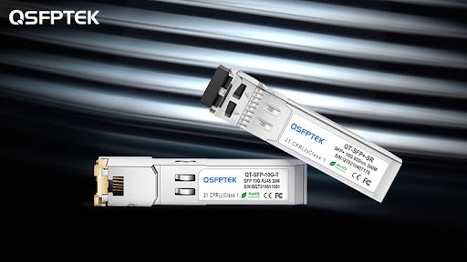
With the implementation of national strategies such as optical advance and copper retreat, fiber-to-the-home, 5G mobile communications, and construction of big data centers, optical fiber communications are becoming more and more important in our lives. Optical and electrical signals are required for optical fiber communication applications such as household optical transceivers (commonly known as “optical cats”), servers and switches in various computer rooms of operators and large data centers, and 4G/5G signal towers. The two-way conversion process of this photoelectric conversion is completed by the optical transceiver integrated module (referred to as “optical module”). According to the SFF-8472 protocol, the international standard for optical modules, in addition to photoelectric conversion, the optical module will also complete other tasks, including module voltage, laser drive current, transmitted optical power, received optical power, and module temperature. Monitoring is used to help the system monitor the working status of the optical module in real-time. Once the optical fiber communication is abnormal, the user can assist in finding the fault point according to the five real-time monitoring parameters. If the optical module monitoring is not accurate, it will lead to misjudgment of the optical fiber communication system, which may interrupt the communication network by mistake or give wrong transmission data.

During mass production or use of optical modules, these monitoring quantities may be inaccurate or abnormal due to the influence of various conditions such as differences in raw materials, processing differences, signal interface differences, and power supply systems. Test the optical modules returned by customers with abnormal receiving monitoring, and find that the abnormal monitoring situation is not constant. For the same module receiving monitoring abnormality, the monitoring information is normal in most cases, after automatic monitoring. In high-frequency refresh software test, hundreds of times of data reading can find that dozens of monitoring information is abnormal, and the abnormal monitoring status is about 1/10. For mass-produced products, it is necessary to find the cause of the abnormality and corresponding solutions.

In order to confirm the cause of the abnormality and find a solution, the module power supply waveform was tested with an oscilloscope. According to the judgment of the noise amplitude in the power supply waveform, the power supply noise was not the cause of the abnormal monitoring; the I2C bus signal when the monitoring was abnormal was also tested with an oscilloscope. The waveform is pure and standardized, indicating that the monitoring abnormality is not caused by the reading error of the I2C bus; in addition, through the comparison test, it is found that different TIAs will have a great impact on the accuracy of receiving monitoring. Accurately selecting the decoupling capacitor connected to the TIA, which can greatly reduce the probability of abnormality; finally, it is also an effective way to solve the abnormality of receiving monitoring by reasonably selecting the coefficients of the monitoring calibration equation through experiments. Therefore, the combination of software calibration and accurate selection of TIA decoupling capacitors can completely solve the abnormal reception monitoring when there is no light.
In the optical module, the receiving calibration caused by TIA noise is not accurate enough. By adjusting the decoupling capacitor connected to the TIA monitoring signal, the probability of abnormal monitoring can be greatly reduced, and the noise that cannot be completely eliminated can be adjusted by adjusting the monitoring offset. , using software to discard part of the analog-to-digital conversion data and get a complete solution. If the noise cannot be greatly reduced by hardware, and the offset adjusted by software is too large, the monitoring accuracy will be greatly reduced. For example, the monitoring accuracy that could have been -35dBm may be reduced to only -25dBm. . Therefore, the hardware solutions and software solutions mentioned in this article need to be used together, which is the most effective solution.


